| Phase IV - STAR ctr.9/2012
Title (Phase IV ): « Structural Design and analysis. Composite Materials R&D »
Period: 21/ 12/ 2013- 20/ 11/ 2014
Phase IV Activities:
• IV.1 CAD design of structural elements/models
• IV.2. FEM simulation on structural elements/models
• IV.3. Selection of the test configurations: material and structure design
• IV.4. Design of the mold for the satellite electronic housing mechanical structure
• IV.5. Creating and customizing the structural materials
• IV.6. Laboratory testing of the proposed materials for structural and mechanical characterization
• IV.7. Drafting of the preliminary manufacturing process
• Management and dissemination
Results:
1.1. CAD design of structural elements/models
3 geometrical designs were developed: CAD I,II and respectively III, with dimensions fixed at: 460 mm x 154 mm x 250 mm. Based on preliminary FEA results a down-selection process was performed based on criterion: weight, accessibility-integration of electronic units and required high mechanical performances mainly in dynamic regime (critical for launching stage), following optimization operations (geometrical) and structural for the CAD -II selected solution. The Final design configuration integrated within its main structure: 3 composite components (laminate type) from CF(₁,₂)RP material: frontal, "L" and "U" shape components, but also metallic elements in aluminium (AA 6068): 2 lateral ribs, stiffeners (for integration and stiffness), one frontal frame (for closing structural assembly and stiffness) and respectively 2 railway plates for the electronic units integration (of the microsatellite). The composite components assembly with the metallic items was performed using aluminium tribo blinde rivets of 3.2 mm diameter (ussualy used in space applications).
1.2. FEM simulation on structural elements/models results
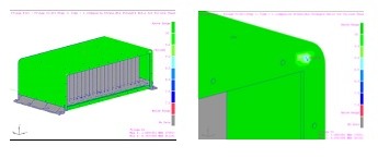
Both static and dynamic(vibration) regime finite element analysis were performed. The minimum safety coefficient for the advanced composite structure was calculated using Hashin fabric theory, which was used also within this study for failure mechanisms assessment for the composite material within the space structure. Example: CAD1-CFRP (static analysis results)

Min. Safety factor distribution (at corner region) within the composite components FOS = 8.3

Failure mechanisms of the composite structure at last ply level (external ply under the Ta foil)
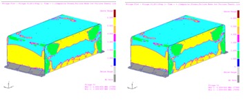
For the modal analysis a simple criterion was chosen, that the first natural frequency of the lightweight composite space structure (integrating electronic units of the microsatellite) to be greater than 100Hz, in order to avoid interferences with the launcher vibration frequencies. For the lateral frequencies vibration range a fundamental frequency higher than 50 Hz is accepted, nevertheless, considering that the final mounting position of the developed structure is not set, for structural security raisons, a first natural frequency higher than 100Hz was required. Exemple: CAD2-CFRP (results of modal analysis)

First 3 vibration modes at resonance of the space structure housing (CAD2 design)
The fundamental vibration frequency of the structure's assembly is at 107 Hz, near 100 Hz. Further, based on the finite element analysis results of the three geometric versions integrating the structural concept High Z-Low Z-High Z, was optimized the CAD-II, obtaining the optimized version of the CAD - Final Design, which comprise the stiffening of the structure (CFRP ribs for the CF(₁,₂)RP composite component "L", respectively "U"). The modal analysis results indicated a first vibration frequency of 115 Hz. The nonlinear static analysis indicated a minimum safety factor >5 for all the studied configurations (aluminium reference and composite structure), higher than 2, requirement indicated in ECSS-E-ST-32-10C Rev.1 (2009) standard for polymeric reinforced structures.
1.3. Test configurations: material and structure design
The materials under study for the manufacturing of structural design were :
- CFRP : UD- EP142-CR509-160-35; CC206/CE662; EP 127-C20-45 T2.
- aluminum (6082-T6) for the lateral ribs/stiffeners (left/right, support plate for the electronic boards, the front rib and for the clamps of the box in the satellite).
- tungsten or tantalum: foils of 0.08 thickness, mechanical and chemical treated to obtain a higher roughness and to ensure a strong interface composite-metal, which is integrated in the hybrid structure, in order to increase the γradiation resistance.
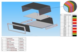
A sketch of the selected structural design, Low Z-High Z-Low Z, is shown in the next picture.

The structure's components and the structural design- section view
Low Z-High Z-Low Z-Final Design
Main strctural materials
EP127-C20-45 (Gurit) CF(1,2)RP with cyanate ester thermoset polymeric matrix reinforced with carbon fiber. The material has a density of 1.5 g/cm³, compared to the reference material AA 6058 (2.8 [g/cm³]). In order to ensure the mechanical strength (and stiffness) required for the launching of the microsatellite (mainly in dynamic conditions, vibration), the reinforcement of the matrix was achieved using high strength and high modulus carbon fiber 3k. Mechanical characterization of the material was accomplished through a experimental test campaign in the laboratory, using a mechanical testing machine Instron 8802 from INCDT COMOTI. The next table shows a review of composite material characteristics obtained.
Property |
Value (RT) |
Standard |
Value (120°C) |
0° Flexural Strength |
910 MPa |
ISO 178 |
840 MPa |
0° Flexural Strength |
49 GPa |
ISO 178 |
47 GPa |
0° Tensile Strength |
760 MPa |
ISO 527-4 |
710 MPa |
0° Tensile Modulus |
59 MPa |
ISO 527-4 |
58 GPa |
0° Compressive Strength |
800 MPa |
EN 2850 |
710 MPa |
0° Compressive Modulus |
48 GPa |
EN 2850 |
41 GPa |
±45° In-Plane Shear Strength |
104 MPa |
EN 14129 |
85 MPa |
±45° In-Plane Shear Modulus |
G₁₂=4GPa |
EN 14129 |
3.9 GPa |
0° Interlaminar Shear Strength |
XILLS=74 MPa |
DMS 2144 |
64 MPa |
Materials used for the developed structural design meet the requirements of ECSS-Q-ST-70-02C and ASTM E595 (developed by NASA) standards concerning the outgassing phenomena for the materials used in space applications. The analysed samples showed a total mass loss (TMP[g cm-2]) <1% and an amount of collected condensed volatile substances (CVCM) less than 0.1%.
In order to ensure a high value of the thermal conductivity of the heat dissipation released by the electronic units, was used a second type of carbon fiber (λ=1000 [W/mK]) as reinforcing phase of the thermoset matrix (cyanat ester).
Tanatalum foil (thikness of 0.08 mm) symmetrical integrated (embeded) in the composite structure (forming a hybrid structure), in order to increase the ionizing radiation resistance (γ).
The aluminium AA 6082-T6 ribs are used to integrate the space structure in the microsatellite to stiffen the structure and to ensure (ionized) radiations shielding and the thermal transfer in vacuum, required for heat dissipation released by the elecronic units of the microsatellite
The structure was partially validated for the impact: Space debris: impact speed: 10 km/s, impact direction:45° from the normal of impacted surface, impactor density: 2.0 g/cm3. Thermal cycling strength was carried through exposure to 10 cycles of 100 minutes [-100;+100°C], in the climatic chamber, Hrel=0%, but in the absence of advanced vacuum environment (critical condition). After exposure the structure showed no degradation or significat structural changes. The exposure period was limited, thus, the stability and dimensional integrity of the structure wasn't damaged. The thermal conductivity of the structure has not been experimental determined. CTE (coefficient of thermal expansion) of the CFRP basic structure is 0.125x10⁻⁶ /K-1, ensuring the necessary dimensional stability, although, a critical issue in the project is the difference between the composite CTE and the metallic inserts CTE (tantalum foil, AA6082-T6 ribs) that can lead to tensions at the interfece during the polymerization process.
Radiation: The level of radiation on low orbit (LEO) at 600 - 900 km altitude: Electrons: 40 [keV] - 5 [MeV], based on AE-8 model; Protons: 100 [keV] - 200 [MeV], based on AP-8 model; X-ray: 0,1 - 10 [keV], according to solar eruptions, from photons with energies of 1-3 [keV]; Photons (Bremsstrahlung): made by radiation deceleration inside the material, contributes to degradation of material coatings; UV: FUV (far ultraviolet): 0,1 [W/m2] or 0,007% of solar electromagnetic radiation; NUV (near ultraviolets): 118 [W/m2] or 8,7% of solar electromagnetic radiation. Neutron bombing: creates collisions that produce punctual defects and material structure deployments. At high energies, they can lead to metallic or nemetallic material brittleness and their expansion, limiting their potential Gamma rays are absorbed by high atomic number and high density materials, but the most important criteria is which determines the material degradation is weight/area rate. Alpha and beta rays are less critical for polymeric materials, because they can be film shielded. Electromagnetic shielding as well as exposure, abrasion due to atomic species and charged particles, especially oxygen atoms, have been studied during this phase.
1.4. CAD Design of the mold for the satellite electronic housing mechanical structure

Exemple: CAD Model mpuld for "L" shape composite component
Mould material: Necuron 701. The selection criteria's: coeficient of thermal expansion CTE, colose to the one of the processed material (CFRP), in order to avoid stress concentrations do to CTE materials mismach, which can aprea during processing; high thermal resistance (polymerization process takes place at 160°C); easy mechanical operations and precision; thermal cycling resitance 9fatigue0; low density (mobility during manufacturing process).
1.5. Customized structural materials Design
Results are integrated in the section 1.3 presentation, above.
1.6. Laboratory testing of the proposed materials for structural and mechanical characterization
30 structural configurations were developed as laminates and samples with thicknesses of 2 mm using autoclave technology and afterwards tested in different regimes. The developed structures were examined before and after exposure to gamma radiations (from 10 to 500 Gy, Ce137 source with 0.4 KGrey/h) to determine the aging effect on the material microstructure and morphology; glass transition temperature (Tg) which sets the maximum temperature of the structure during service ; thermal conductivity (k) ; specific heat (c) ; thermal expansion coefficient (CTE) ; surface properties of the material (adherence, adhesive strength) ; tribological characteristics (friction coefficient/resistance, wear resistance) ; mechanical performances (static regime).
Several type of tests and analysis were performed : mechanical tests (shortly described in section 1.3 above) ; thermogravimetric analysis and dynamic differential calorimetry (TG-DSC) according to SR-EN 11357 : 2000 ; thermal diffusivity analysis, thermal conductivity analysis and specific heat analysis, thermal expansion coefficient analysis where it has been observed that an increase of radiation dose determines a decrease of temperature at which phase transformations in composite takes place, but in the same time the thermal transformation range become wider.
1.7. Preliminary manufacturing process- work protocol
The mould preparation operations were defined: grinding, cleaning, applying gelcoat, planarity and roughness measurement, etc., components (CF(1,2)RP structures: "L", "U", front plate): dimensions, structural design, structural or assembly elements, ribs positioning (number of plies, dimensions, sequence, etc.); main structural materials: materials (Tantalum foil, CF(1,2)RP composite, Aluminum ribs). CF(1,2)RP composite: number of plies, reinforcing thermoset resin volumetric fraction, ply thickenss, fiber orientation, ply dimensions, tantalum foil, mechanical and chemical surface treatment (adherence to the main composite materials structure, aluminum ribs/stiffners, dimensional control after mechanical operations, positioning within the structure, assembly method, etc. Likewise operations and processes: lay-up, vacuum bagging (basic and auxiliary materials) and curing cycle (autoclave technology), were defined.
Management and diseemination
Two technical meetings were organized: No.6/09.05.2014 and No.7/31.07.2014. The webpage of the project ADCOSSPA was updated (accesible on http://www.comoti.ro, in romanian and english) with the most recent results of the project. The ADCOSSPA team participated to the annual conference organized by contracting authority ROSA, "Romanina Space Week", 12-16 May 2014, bucharest, Romania.
Papers and conferences:
- scientific paper "Equipment Design and Structural Analysis of CFRP Electronics Housing vs. Aluminum Electronics Housing for an ADPMS" autori: Sorin Draghici, Florin Baciu, Raluca Voicu, Anton Hadar la conferinta ICSAAM 2013, The 5th International Conference on Structural Analysis of Advanced Materials 23 - 26 September 2013, Island of Kos, Grecia.
- scientific paper "Influence of advanced vacuum and temperature variations on the behavior of subassemblies of a satellite" Sorin Draghici, Florin Baciu, Raluca Voicu, Anton Hadar la conferinta 6th International Conference "Biomaterials, Tissue, Engineering&Medical Devices", 17-20 September 2014, Constanta, Romania
- scientific paper "Modelarea comportamentului la lansare a unui subansamblu din componenta unui satelit" Sorin Draghici, Florin Baciu, Raluca Voicu, Anton Hadar, Academia Oamenilor de Stiinta din Romania, Proceeding Sesiunea stiintifica de Primavara, 9 May 2014
- scientific paper "Structuri din materiale compozite avansate dezvoltate prin tehnologii performante pentru industrii de varf: aeronautica si spatiul la Insitutul Na?ional de Cercetare-Dezvoltare Turbomotoare COMOTI" Stiinta si Tehnica magazine, no.41 November /2014
Conclusions:
The objectives of Phase IV have been achieved. Based on the results from Phase III of the project, after establishing the final specific set of requirements for the space structure which integrates the electronic units in a microsatellite, the structural design and geometry (Final Design) has been defined and the methodology for designing the space composite structure has been created including the constrains for radiation shielding, first natural vibration frequency, structural integrity, electric resistivity and in the same time to limit the shape distortions generated by thermal loads (thermal cycles). Composite and metallic material selection has been performed for the space structure; different types of material configuration were tested, followed by material purchase. Validations of the structural design and of the selected materials for the space structure have been achieved during Phase IV, based on numerical simulations (FEA) and on the results from laboratory tests. Starting from the optimal design (CAD of structure elements), the mould required for the manufacturing process of the composite space structure has been designed. Likewise, during the Phase IV of the project, the preliminary manufacturing protocol for the mechanical compositespace structure hosting the electronics of a microsatellite, has been defined.
|